
| |
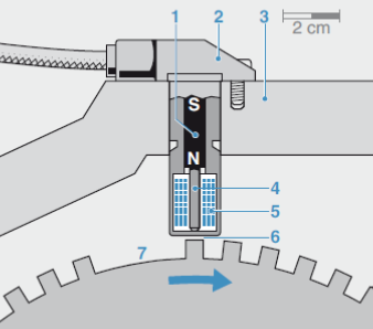
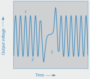
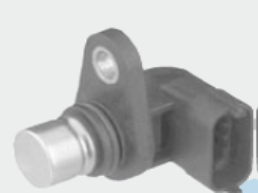
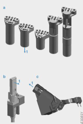
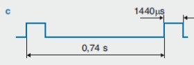
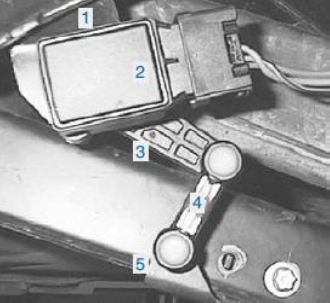
| Engine Velocity (Crankshaft) Sensor | |
| Measuring the speed of engine and determine the crankshaft position (position of the pistons) for the engine management system. Reference Mark is used to defined crankshaft position and synchronize the control unit. | |
 |  |
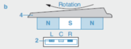
| Engine Phase (Camshaft) Sensor | ||
| Indicate the piston (compression or exhaust) stroke to trigger the ignition and fuel injection. | ||
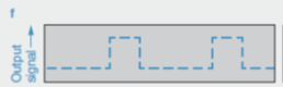
| a:
b: Output signal | 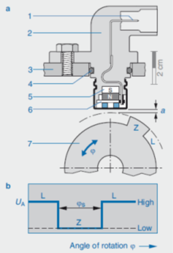 |
|
| Speed Sensors for Transmission | ||
| Detect the speed of the turbine/output shaft in AT, the primary and secondary pulleys in CVT, input/driving shift in DKG, rotation direction is necessary for high-end products. | ||
|
Customized design including ASIC, package,mechanical and magnetic interface due to diversity of the transmissions. | 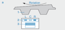 | Trigger Wheel Type |
 | Multipole Wheel Type | |
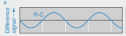 | Differential signal btw R/C | |
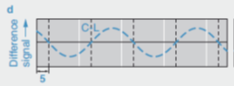 | Differential signal btw C/L | |
 | Output signal for CW | |
 | Output signal for CCW | |
| Wheel Speed Sensors | ||
| Measure the vehicle wheels speed to controls the braking force individually at each wheel to prevents the wheels from locking up (with ABS) or from spinning (with TCS or ESP), and to calculate the speed/traveled distance. | ||
|
|  | CCW Signal |
 | CW Signal | |
 | Stationary Signal | |
 | Self-diagnosis Signal | |

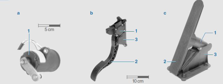
| Acceleration Pedal Sensor |
| Recording the travel or the angular position of the accelerator pedal for the electronic throttle control (ETC). |
|
|
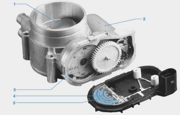
| E-Throttle Sensor |
| Responding the angle position information of the throttle valve to ECU to regulate the intake air mass for a specific air-fuel mixture. |
|
|
| Steering Angle Sensor | |
| Monitor the driver’s input by continuously measuring the position and turning rate of the steering wheel and report the information to ECU, in order to control various driver-assist systems such as ESP, EPS and Active Steering together with the information from other sensors. | |
|
|
The passenger-car steering wheel turns through ±720° (a total of 4 complete turns), conventional angular position sensors can only measure maximum 360°, so 2 angle sensors are needed. |

| Axle Sensor | |
| Two angle sensors on front/end axle record the bodywork’s tilt angle resulting from the vehicle loading, braking/acceleration for adjusting the vehicle’s headlamp range automatically, or adjusting the chassis height via active suspension. | |
|
|
|
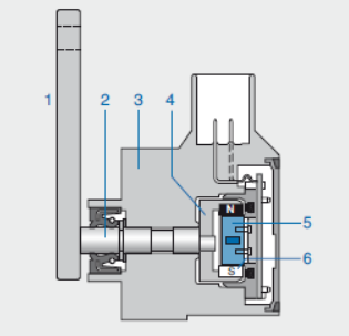
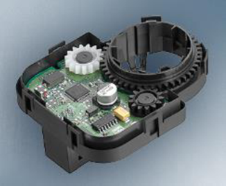
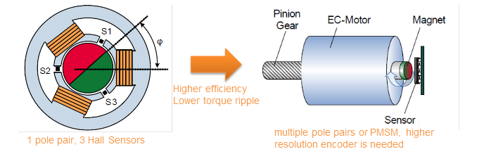
| Magnetic Encoder for BLDC Motor | |
| Measure the rotor position for current commutation in the stator to achieve high power efficiency and lower torque ripple. | |
|
| |
| ||||||||